 HOME
HOME-
SOLUTIONS
-
DOCUMENTS
-
CORPORATE
Share
Estap Datacenter Solutions offer high performance, continuity of work and energy efficiency. Estap provides managed, scalable and high efficiency solutions to datacenter projects. Thanks to ''Isolated Cold & Hot Aisle'' applications, Estap provides high-energy efficiency and low operating costs. Power distribution units -PDUs- serve as a connection point of active devices. PDUs provide energy management and monitoring.
PDU software offers remote access control for environment monitoring and cooling systems.
There is a virtual task of datacenters that requires reliable,flexible and scalable infrastructures with guaranteed performance. Datacenters quarantees a continuity of service quality and additionally, ensures energy savings.
Data Center
What is Data Center?
A data center is a facility used to house computer systems and associated components, such as telecommunications and storage systems. It generally includes redundant or backup power supplies, redundant data communications connections, environmental controls (e.g., air conditioning, fire suppression) and security devices. Large data centers are industrial scale operations using as much electricity as a small town and sometimes are a significant source of air pollution in the form of diesel exhaust.
About Data Centers
Due to the large market potential many solutions arise for each aspect of Data center design: Cooling, Power, Management and Infrastructure, resulting in a large range of solutions. This creates another issue: When to select what kind of products in what type of situation suitable for what type of Data center, commercial, corporate, small or large?
Following fundamental principles, especially during the design, will create a solution that pays-off during the whole lifetime of a Data center. In terms of energy efficiency and the way it complies to its function and/or business goals. An optimal performing Data center will create a stronger position in the market or within the company.
Why Do We Need Data Centers?
Because of below listed reasons, Data Centers are always better and useful.
- High internet connection speed.
- Improved electricty network and back-up power system.
- Security.
- Professional cooling.
- Environmental monitoring and controling.
Business Models in Data Center
There are different types of business models in Datacenter business. One is providing everything A to Z; the other is only providing operational services.
| TYPE OF BUSINESS | DESCRIPTION |
|---|---|
| Operator | Operates the entire data center from the physical building through to the consumption of the IT services delivered. |
| Colo Room provider | Operates the data center for the primary purpose of selling space, power and cooling capacity to customers who will install and manage racks and IT hardware. |
| Colo provider | Operates the data center for the primary purpose of selling space, power and cooling capacity to customers who will install and manage IT hardware. |
| Colo customer | Owns and manages IT equipment located in a data center in which they purchase managed space, power and cooling capacity. |
| Managed service provider (MSP) |
Owns and manages the data center space, power, cooling, IT equipment and some level of software for the purpose of delivering IT services to customers. This would include traditional IT outsourcing. |
| Managed service provider in Colo |
A managed service provider which purchases space, power or cooling in this data center. |
Tier Levels
As being a Global Authority, Uptime Institude, in 2005, has launched some standards. The reason is to improve Data Center knowledge and raise the quality of Data Center to gain efficiency.
Tier I: Non-Redundant
Dedicated Data Center Infrastructure Beyond Office Setting
Tier I solutions meet the data center owner’s or operator’s desire for dedicated site infrastructure to support information technology (IT) systems. Tier I infrastructure provides an improved environment compared to an office setting and includes a dedicated space for IT systems; an uninterruptible power supply (UPS) to filter power spikes, sags, and momentary outages; dedicated cooling equipment that won’t get shut down at the end of normal office hours; and an engine generator to protect IT functions from extended power outages. Examples of industries that will benefit from a Tier I facility are real estate agencies, the hospitality industry and business services such as lawyers, accountants, etc.
Tier II: Basic Redundant
Power and Cooling Systems Have Redundant Capacity Components
Tier II facility infrastructure solutions include redundant critical power and cooling components to provide an increased margin of safety against IT process disruptions that would result from site infrastructure equipment failures. The redundant components are typically power and cooling equipment such as extra UPS modules, chillers or pumps, and engine generators. This type of equipment can experience failures due to manufacturing defects, installation or operation errors or over time, worn-out equipment.
Examples of industries that select Tier II infrastructure include institutional and educational organizations because there is no meaningful tangible impact of disruption due to data center failure.
Tier III: Concurrently Maintainable
No Shutdowns for Equipment Replacement and Maintenance
Tier III site infrastructure adds the capability of Concurrent Maintenance to Tier II solutions. As a result, a redundant delivery path for power and cooling is added to the redundant critical components of Tier II. So that each and every component needed to support the IT processing environment can be shut down and maintained without impact on the IT operation.
Organizations selecting Tier III infrastructure typically have high-availability requirements for ongoing business or have identified a significant cost of disruption due to a planned data center shutdown. Such organizations often support internal and external clients 24 x Forever, such as product service centers and help desks.
Tier IV: Fault Tolerant
Withstand a Single, Unplanned Event, e.g., Fire, Explosion, Leak
Tier IV site infrastructure builds on Tier III, adding the concept of Fault Tolerance to the site infrastructure topology. Fault Tolerance means that if/when individual equipment failures or distribution path interruptions occur the effects of the events are stopped short of the IT operations.
Organizations that have high-availability requirements for ongoing business (or mission imperatives), or that experience a profound impact of disruption due to any data center shutdown, select Tier IV site infrastructure. Tier IV is justified most often for organizations with an international market presence delivering 24 x Forever services in a highly competitive or regulated client-facing market space, such as electronic market transactions or financial settlement processes.
Key Elements of Data Center
1. Power and Electrical Infrastructure
2. Cooling
3. Security, Fire Detection-Suppression and Access Control
4. Network/Cabling
5. Knowledge
6. Housing, Cabinets and Corridor Solutions.
Power in Data Center
Sometimes, 2 seconds energy interruption in Data Centers will cause many problems all over the world. Or cause of surge equipments will broken down. So to have a good quality energy and continuity on power, electricty has to be design and build according to standarts. Also power using volume and power saving is a world wide issue to home better future.
Power Usage Effectiveness (PUE)
The Power Usage Effectiveness (PUE) of a data center is a metric that is used by engineers and project managers of data center to define the energy efficiency of a data center (over time) and to specify in what areas and through the use of which technologies certain improvements to the energy efficiency could be made.
Although a mature level of PUE information gathering is preferable in the end (Master PUE), one could easily start off with Basic PUE principles and gradually move towards an Advanced PUE and then a Master PUE level. Basic PUE monitoring principles can be implemented using simple tools that are low on initial investments, for example with an instrument like a Current Clamp Meter, which is just a general electrician tool.
A PUE is an index number. Generally speaking a traditional server room design will generate a PUE of about 2.0, sometimes even higher. The closer to 1.0 it gets, the more energy efficient a server room set-up will be. However, a result of 1.0 is hardly possible as it would imply an absence of overheads such as lighting and so on. An overall PUE figure can be subdivided into several location specific sub figures, so adequate and prioritized measurements can be taken in locations that need attention.
A PUE is an index number. Generally speaking a traditional server room design will generate a PUE of about 2.0, sometimes even higher. The closer to 1.0 it gets, the more energy efficient a server room set-up will be. However, a result of 1.0 is hardly possible as it would imply an absence of overheads such as lighting and so on. An overall PUE figure can be subdivided into several location specific sub figures, so adequate and prioritized measurements can be taken in locations that need attention.
The definition of a PUE is as follows: PUE=Total Facility Power/IT Equipment Power
Tips to Lower PUE
Monitoring first of all is a prerequisite to start lowering your PUE figure, otherwise you will never know where to start your quick win efforts and what results it will bring. After having a PUE monitoring system installed one can start picking the low hanging PUE fruits. Not every low hanging fruit will be applicable for every data center in the market, but generally speaking the following actions could be taken to have some quick wins.
• Installing Cold Corridors
Complete separation of hot and cold airflows, achieved by enclosing the roof section between opposing data center cabinets on the cold aisle with glass panels. Both ends of the cold aisle are sealed off using sliding doors to contain the air. Installing Cold Corridors together with other measures will lead to significant efficiency improvements.
• Installing Free Cooling
The use of Free Cooling is not applicable for every data center environment. Especially within existing and full operational data center environments installing Free Cooling would be a tough job to realize. For new data center development however one should definitely have a look at this option. When Free Cooling is actually being installed it is very important to have the system tuned correctly. It happens quite often that Free Cooling is being installed but not tuned the way it should, with the result that the investment in Free Cooling doesn’t pay off.
• Reduce air leakage
Cabinets within a Cold Corridor system can be easily equipped with blanking panels, so cooling air is not wasted at spots where no equipment is being installed yet. The use of blanking panels makes sure the only route for air flows is through the equipment. Another way to reduce leaks is by using air sealed racks.
• Adjusting fan speed of cooling systems
Especially when one is using Cold Corridors, the fan speed of cooling equipment can be set at lower levels than one is probably used to. That’s because cool air is more equally and efficiently being divided within a Cold Corridor system.
• Allowing higher temperature set points will also lower your PUE figure
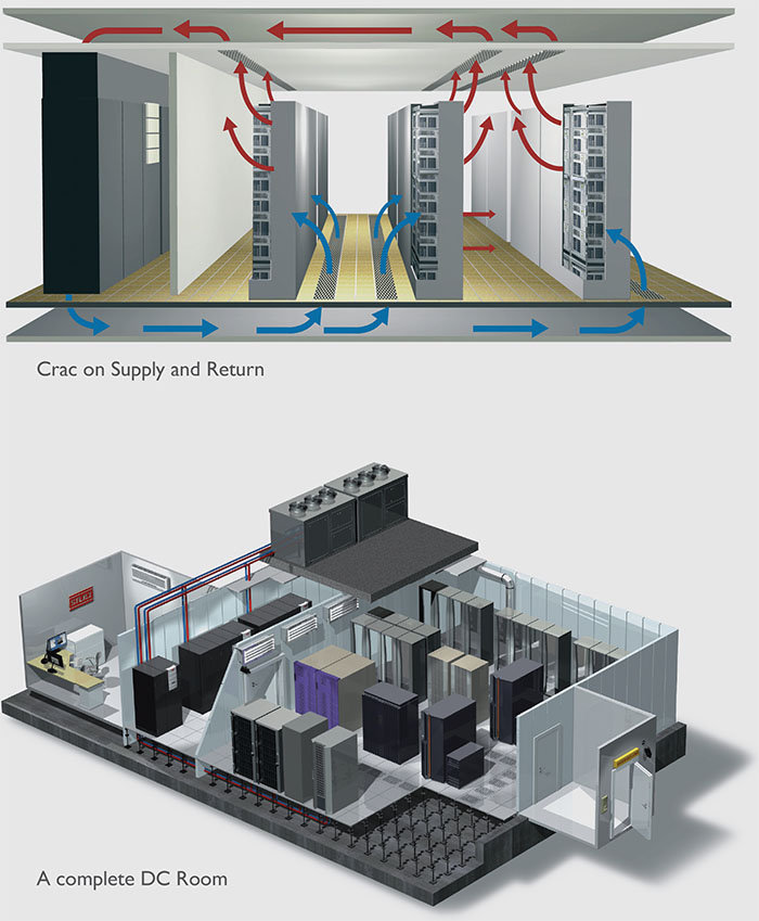
Separation of hot and cold air avoids hotspots and therefore temperature set points can be higher without compromising the server inlet temperature. Setting CRAC units at supply air temperature instead of return air temperature before the introduction of hot and cold aisles data center CRAC units were set at room temperature i.e. 22˚C. This is return (hot) air temperature. In a Cold Corridor DC the supply air temperature to the servers should be controlled, not the return air temperature. Get in contact with the CRAC unit manufacturer or installer to check whether this is possible.
Cooling Solutions
About Cooling
Data Center technology has arrived to a point of no return in the recent times. The servers used in them have evolved and have reduced in physical size but have increased in performance levels.
The trouble with this fact is that it has considerably increased their power consumption and heat densities. Thus, the heat generated by the servers in Data Centers is currently ten times greater than the heat generated by them around 10 years back; as a result, the traditional computer room air conditioning (CRAC) systems have become overloaded. Hence, new strategies and innovative cooling solutions must be implemented to match the high-density equipment. The rack level power density increase has resulted in the rise of thermal management challenges over the past few years. Reliable Data Center operations are disrupted by hot spots created by such high-density equipment.
Some of the main Data Center challenges faced in the current scenario are adaptability, scalability, availability, life cycle costs, and maintenance. Flexibility and scalability are the two most important aspects any cooling solution must possess; this, combined with redundant cooling features, will deliver optimum performance.
The two main Data Center cooling challenges are airflow challenge and space challenge. These challenges can be overcome with the use of innovative cooling solutions.
ASHRAE, American Society of Heating, Refrigerating and Air-Conditioning Engineers, Inc, whom is defining standarts, adviced the recommended environment conditions as like in below chart in 2008.
| ENVIRONMENT | CONDITION |
|---|---|
| Low End Temperature | 18°C (64.4 °F) |
| High End Temperature | 27°C (80.6 °F) |
| Low End Moisture | 5.5°C DP (41.9 °F) |
| High End Moisture | 60% RH & 15°C DP (59°F DP) |
2012 ASHRAE Environmental Guidelines for Datacom Equipment.
Cooling Design Models
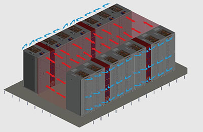 Hot Aisle Containment
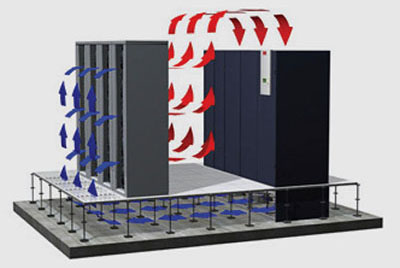
Racks will be positioned in rows back to back. The hot aisle in between racks will be covered on the top and at the end of the rows and ducted back to the CRAC unit. A full separation between supply and return air is achieved. Cold supply air will be delivered into the room and the room itself will be at a low temperature level.
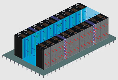 Cold Aisle Containment
Racks will be positioned in rows front to front. The cold aisle in between racks will be covered on the top and at the end of the rows. A full separation between supply and return air is achieved. Cold air will be supplied through the raised floor into the contained cold aisle; hot return air leaves the racks into room and back to the CRAC unit. The room itself will be at a high temperature level.
 Direct In-Rack Supply, Room Return Concept
Cold supply air from the CRAC enters the rack through the raised floor directly in the bottom front area. Hot return air leaves the rack directly into the room. A full separation between supply and return air is achieved. The room itself will be at a high temperature level.
 Room Supply, Direct Rack-Out Return Concept
Cold supply air from the CRAC enters the rack through the room. Hot return air leaves the rack through a duct and suspended ceiling directly back to the CRAC unit. A full separation between supply and return air is achieved. The room itself will be at a low temperature level.
Close coupling of CRAC units and Racks on Supply and Return Side
Cold supply air from the CRAC enters the rack through the raised floor directly in the bottom front area. Hot return air leaves the rack through a duct and suspended ceiling directly back to the CRAC unit.
Cooling Design
Hot Aisle and Cold Aisle solutions have same cooling power and power efficiency. Just are different installation and different ideas of different Data Center drivers on the way of same goal.
Cooling Units
What is CRAC Unit?
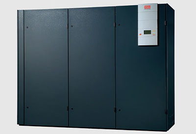
Computer Room Air Conditioning (CRAC) unit is a device that monitors and manages the temperature, air distribution and humidity in a network room or data center.
Mini Crack UnitMiniSpace DXCooling capacity 5 kW to 23 kW Cooling systems A/GDirection of airdownflow / upflow
MiniSpace CWCooling capacity 11 kW to 28 kW Cooling systems CWDirection of airdownflow / upflow
The advantages at a glance
- Maximum cooling performance with minimum floor space
- Air-cooled, water/glycol-cooled and chilled water versions available
- Units as downflow and upflow versions
- Simple installation and maintenance through doors on the front air filtering with filter class EU 4
- Steplessly adjustable EC fan
- C7000 IO controller for controlling and monitoring the air-conditioning system
- Automatic switchover to redundant standby units in the event of problems
- Modbus preinstalled
- Continual recording of measured values
Options
- C7000 Advanced user interface with LCD graphic display, RS485 interface and other preinstalled data protocols for linking to building services management systems
- Communication via SNMP/HTTP IP protocols
- Humidifier/heating
- R134a high-temperature refrigerant
Crack Unit
Dimensions
WxHxD in mm
Size 1: 950 x 1980 x 890
Size 2: 1400 x 1980 x 890
Size 3: 1750 x 1980 x 890
Size 4: 2200 x 1980 x 890
Size 5: 2550 x 1980 x 890
Size 6: 3110 x 1980 x 890
Size 7: 3350 x 1980 x 890
* Size 7 is only available as a downflow version
CyberAir 3 DX and Dual-Fluid Units, single-circuitCooling capacity 18 kW to 54 kW Cooling systems A/AS/G/ACW/GCW Direction of airdownflow / upflowSizes1-3; AS only 2
CyberAir 3 DX and Dual-Fluid Units, dualcircuit
Cooling capacity 40 kW to 105 kW Cooling systems A/AS/G/ACW/GCW Direction of airdownflow / upflow Sizes 3-5; AS only 3,4
CyberAir 3 GE Units, single-circuit
Cooling capacity 18 kW to 55 kW Cooling systems GE/GES Direction of airdownflow / upflow Sizes1-5; GES only
CyberAir 3 GE Units, dual-circuit
Cooling capacity 41 kW to 104 kW Cooling systems GE/GES Direction of airdownflow / upflow Sizes1-5; GES only 4,5
CyberAir 3 CW
Cooling capacity 30 kW - 214 kW Cooling systems CW Direction of airdownflow / upflow Sizes1-5; 7*
CyberAir 3 CW2
Cooling capacity 27 kW to 137 kW Cooling systems CW2 Direction of airdownflow / upflow Sizes1-5; 7*
CyberAir 3 CWE/CWU
Cooling capacity 39 kW to 237 kW Cooling systems CWE/CWU Direction of airdownflow Sizes1-5; 7; 8


